Click for full-size photo
Mark Kelly's Balanced Phono Preamp
My design goals here were for a vacuum-tube based phono preamp with enough gain for moving magnet cartridges, balanced input and output, low capacitance loading and RIAA equalisation accurate to within 1%. I had a couple of goes at this - the first was a loose adaptation of JC Morrison's "Siren Song" (ref 1) with a higher gm front end. This worked OK, but I was convinced I could do better, so I scrapped it and started again. The new design is also heavily influenced by JC's work, with the most significant departure being the JFET front end.I chose a cascode first stage because the cascode topology eliminates Miller capacitance and I wanted to keep total capacitance down to the values recommended by Futrell in his excellent article (ref 2). I don't like vacuum-tube cascodes much; if I'm going to have to use a cascode, I reckon I might as well go all the way and go solid state. If the idea of hybrids horrifies you, by all means, change the front end to a V/V/TT cascode. You could use any of the high-perveance vacuum tubes intended for this use, or even a pair of ECC86 /6GM8s which would run quite happily from a 48V supply.
To keep noise down and help with balance I decided to use dual monolithic high-transconductance 2SK389 JFETs in a balanced configuration with an active BJT tail. The 2SK389 has an input capacitance of about 30pF but in a balanced configuration that's the equivalent of 15pF between phases. Assuming the cartridge has self-capacitance about 25pF and adding in the measured 35pF of the arm cables gives me a total of 75pF across phases.
With an assumed 0.5H of cartridge inductance, a 50k load resistance will result in a Q somewhere around 0.6, roughly midway between the Bessel and Butterworth responses. The cartridge values were taken from the Futrell article which also explains the termination Q calculations. Note that the cartridge load of 50k is split between phases for balanced input so the input resistors are 24k9 each. Lots of my favourite music was recorded in the mono era, so I included a switch for mono mode.
To help with balance I bought a dozen 2SK389s and sorted them to obtain two pairs which had matching between halves of better than 1% and matching between pairs better than 2% at my intended operating point. I also built a bias adjustment into the gate circuits of the top FETs of the cascodes which allows me to tune each input for highest CMRR (common mode rejection ratio). You don't have to use the same type of FET for the top and bottom halves of the cascode but since I'd bought a dozen of the things I thought I might as well. The current through the cascode is set by the active BJT CCS in the tail to give 8mA total for 4 mA per side.
The FETs have current gain of around 20mS at 4mA so a drain resistor of 2k49 will give gain near to 50x. The gates of the top FETS are tied to a voltage divider which holds them at +10V so the drain to source potential across each half of the cascode is about equal. The input stage ended up with a gain of 55x (about 35dB), bandwidth from DC to light, balance between channels approximately 1.5% (0.2 dB), a clipping level of 12.5V RMS and very low noise. The bandwidth worried me, as it is an invitation to RF interference and increased noise, so I inserted a small cap between the drain loads as shown.
Click for full-size schematic diagram
The input stage is fed from a bank of sealed lead acid (SLA) batteries which provide -6V for the tail and +30V for the drains. As mentioned above this stage could be substituted with a V/T cascode. A good example would be a cascode based on the ECC 91/6J6 with 220 V B+ supply, 12k plate resistors, upper grid biased to +75V and an 8mA CCS. This will entail changes to the rest of the circuit and I will sketch those changes in as we go through, but you should note that I haven't built the ECC91 front end, so there may be errors in my descriptions.
The design of any RIAA equalization network is a game of finding the least awful compromise between the various aspects. The gain levels need to be set with an eye to keeping signal levels clear of the noise floor and at one end and below device clipping points at the other. High resistor values allow the use of smaller (better) capacitors but increase thermal noise. Low resistor values mean that active device Zout becomes a larger fraction of the series impedance in the RIAA filters, reducing accuracy.
Every designer negotiates their own path through this maze. One aspect which needs careful consideration is that general filter theory assumes that the source has zero impedance and sink has infinite impedance. Neither of these is the case in real world circuits. In this design you will note that all of the RIAA stages are directly coupled to each other. This considerably simplifies the design of the RIAA network as no account need be taken of the series elements represented by coupling capacitors or the shunt elements represented by the grid resistors present in RC coupled stages.
With lots of clean gain in my input stage I decided to put the network with the 3180 usec and 318 usec time constants first to provide maximal attenuation before the grids of the intermediate gain stage, which is the most likely to be driven to clipping. This also gives the advantage that the filter with the larger time constants (which, ceteris paribus, will use a larger capacitor) is ahead of the gain stage with the larger input Miller capacitance so that impact of the Miller capacitance, which shunts the RIAA network, will be lessened.
One note regarding translating between filter values calculated for single ended circuits and balanced circuits: in a full balanced circuit the "effective value" of the shunt components connected between phases is that of a series pair connected with a "virtual earth" at the centre. Thus, for capacitors the value doubles, and for resistors the value halves.
To calculate the RIAA value I used Hagerman's AnyEq calculator at http://www.hagtech.com/equalization.html. I had a bunch of 68nF MIT polystyrene film / tinfoil caps left over from the first power amp I built so I selected amongst those with a capacitance meter to get a pair of caps which were closely matched - they measured at 67.7nF and 67.8nF respectively.
Using the larger of the two values seems sensible as I can always add a small bypass to bring the other one up. Plugging 135.6nF (double the value) for Ca into the RIAA gave me Ra = 21k1 and Rb = 2k35. Since the FET stage has a Zout equal to its drain resistor value of 2k49 this meant I needed 18k6 for Ra, I used 18k7 as the closest value. Since Rb halves I needed 4k7 so I used 4k74.
The input Miller capacitance for the following stage is about 35pF, adding this to the 135.6 nF capacitor value I still end up with the same resistor values. The time constant of the parasitic filter formed by this and the series resistance is around 750ns, more than two orders of magnitude below the desired time constants so I ignored it.
The following stage is directly coupled to the grids of a pair of 6021 twin triodes. No, that's not a misprint, they are 6021/ECC70s, not 6201/ECC81s. These are subminiature types which I bought to use as the first stage in my first phono preamp, and are about 9.5mm (3/8") in diameter and about 26mm (a little over 1") long.
The 6021s feature fairly high transconductance (5mS) and fairly high mu (35), and having been designed for subminiature avionics applications, they are very robust and vibration resistant. They can suffer from short life due to the high dissipation per unit glass area so you need to take precautions to cool them. - see later regarding the mounting arrangement to help with this.
One interesting feature of the 6021s is that, having been designed for avionics and portable communications where time to readiness is very important, the cathodes get to operational temperature in about two seconds flat. If you don't want to use these dinky little things there are a couple of 7 pin twin triodes which would be fine - you could try either E90CC/5920 or ECC91/6J6A. The E90CC option will also improve overload margin by about 6dB, although I have never managed to overload this amp and my Grace F9E is a fairly "hot" cartridge.
If you use the ECC91 cascode front end you will have great difficulty direct coupling - I suggest you abandon it and use RC coupling instead. Use the biggest and best coupling capacitor you can afford and a high value grid resistor - 1 megohm for preference.
The 6021s are configured as Schmitt phase splitter/differential amplifiers with active BJT CCS tails and 20k plate load resistors, fed from the 210V B+ via a 500R pot to allow fine tuning of CMRR. The CCS tails are set at 9mA for 4.5mA per side. The grids are at the potential of the input cascode drains (20V) so the cathodes are at about 21V giving lots of headroom for the CCS. Plate to cathode voltage is about 100 volts which is near the design centre for these subminiatures.
Again, if you use the V/T front end, these values will need to be changed - the plate voltage is probably OK but you will need to tie the CCS to an appropriate negative voltage. One thing I do in this sort of situation is run the heaters between ground and -6.3V and use the negative heater rail as a tie point.
For the second RIAA filter I used small polypropylene 1nF film and foil caps with polypropylene 5-65pF trimmer caps in parallel. The idea here is to set the RIAA resistor value including the Zout of the V/T so that the Zout can change over a range of 10% or more but I can still keep the RIAA within 1% by altering the shunt capacitance. Of course I could use variable resistors in the series legs but with a balanced design I need one per phase so the adjustment gets tricky.
Using a 1nF cap and the mid range value of the trimmer (35pF) and plugging 2.07nF into the RIAA calcs gave me Rc = 34.7k, with Zout of 5k4 I needed 29k3 so I used 29k4. Rd is the notional fourth constant, the calculator gave me 1k54 but again this is across the phases so I used 3k. The input capacitance of the following cathode follower stage is only about 2 pF so again I ignored this.
Note that the Zout of the Schmitt phase splitter used here is not the one you will find in most analyses of this circuit - including the one I wrote myself for Glass Audio magazine nearly ten years ago. In fact it wasn't until I started writing this article and was forced to ponder why the first version of the RIAA hadn't worked correctly that I realized that the balanced Z out of an SPS is equal to that of the equivalent grounded cathode stage. My thanks to Henry Pasternak, whose observations on the concertina phase splitter on the Audio Asylum "Tube DIY" board pointed the way here. The values above were calculated "after the fact". I actually built the thing with different values, expecting the higher Zout. I had to add some extra capacitance after the measurements came out wrong.
An interesting side note - this also means that a Schmitt phase splitter has lower Zout for balanced components than for unbalanced, so a Schmitt phase splitter with a balanced series filter after it should have better noise performance and lower distortion than the equivalent plate-loaded grounded cathode stage.
The output stage is a pair of 6BQ7As configured as active loaded cathode followers. Again these are directly coupled from the plates of the preceding stage so that the grids sit at about 135V and the cathodes around 140V. For those not familiar with the 6BQ7A it is a 9 pin twin triode originally designed for cascade TV service and is a little like a lower gm version of a 6DJ8/ECC88 but without the "shrieking" sound quality I associate with 6DJ8s.
I'm running these at around 6mA per side, the tail being provided by a higher voltage/higher dissipation version of my favoured BJT cascade CCS. Since the output is sitting at cathode potential you,ll need some form of DC blocking (cap or transformer) to prevent your line amp being fried. I used Axon tin foil polypropylene film coupling caps of 0.68 uF. These are the only series caps in the phono preamp.
Click for full-size schematic diagram
The power supply is fairly simple as it derives B+ from my existing preamp (at approx 270V DC) and uses batteries for everything else. The B+ is further filtered with a series CCS/shunt capacitor followed by a series resistor/shunt voltage regulator composed of a series pair of glow diodes. I originally planned to use an active regulator here but a couple of virtual conversations with Lynn Olson convinced me that wrapping a zero feedback class A circuit inside a high feedback active shunt reg circuit was counterproductive.
The CCS is set for 55mA which allows 15mA for the glow diodes (VR tubes for North Americans). The capacitor value of 13.3uF is a compromise between getting the time constant down and fitting the caps into the box. I had four 3.3uF 250V metallised polypropylene caps which had been intended for a speaker crossover so I used them. The compensation circuits around the glow diode pair are to ensure that the lower one strikes and to shunt the equivalent series inductance of the glow diodes. Glow diodes have quite high equivalent series inductance (approximately 4 mH for most of the common ones) and are therefore not much use for audio unless this is compensated.
Unfortunately you can't just stick a big capacitor in parallel for three reasons. Firstly, the cap will charge up to the supply voltage and then discharge down to the strike voltage when the diode strikes thus dumping a big and possibly destructive current pulse through the diode. Secondly, in some circumstances a cap bypass will form a nice relaxation oscillator as the charge/discharge cycle above repeats endlessly. Third, the cap and the series inductance form a parallel resonant circuit with a fairly high Q peak right in the audio frequency range. The best compensation circuit is the one shown, where the resistor acts to damp the Q of the circuit and slow down the discharge of the cap. Since all the stages are balanced/differential I probably don't need the amount of filtering I have but the glow diodes are pretty.
The major complexity in the power supply is the provision of five separate current limited constant voltage SLA battery charging circuits which are switched in when the amplifier is off. The final circuit is shown in fig 2. Note that the heater supply for the 6BQ7s is biased above ground to reduce heater/cathode insulation stress.
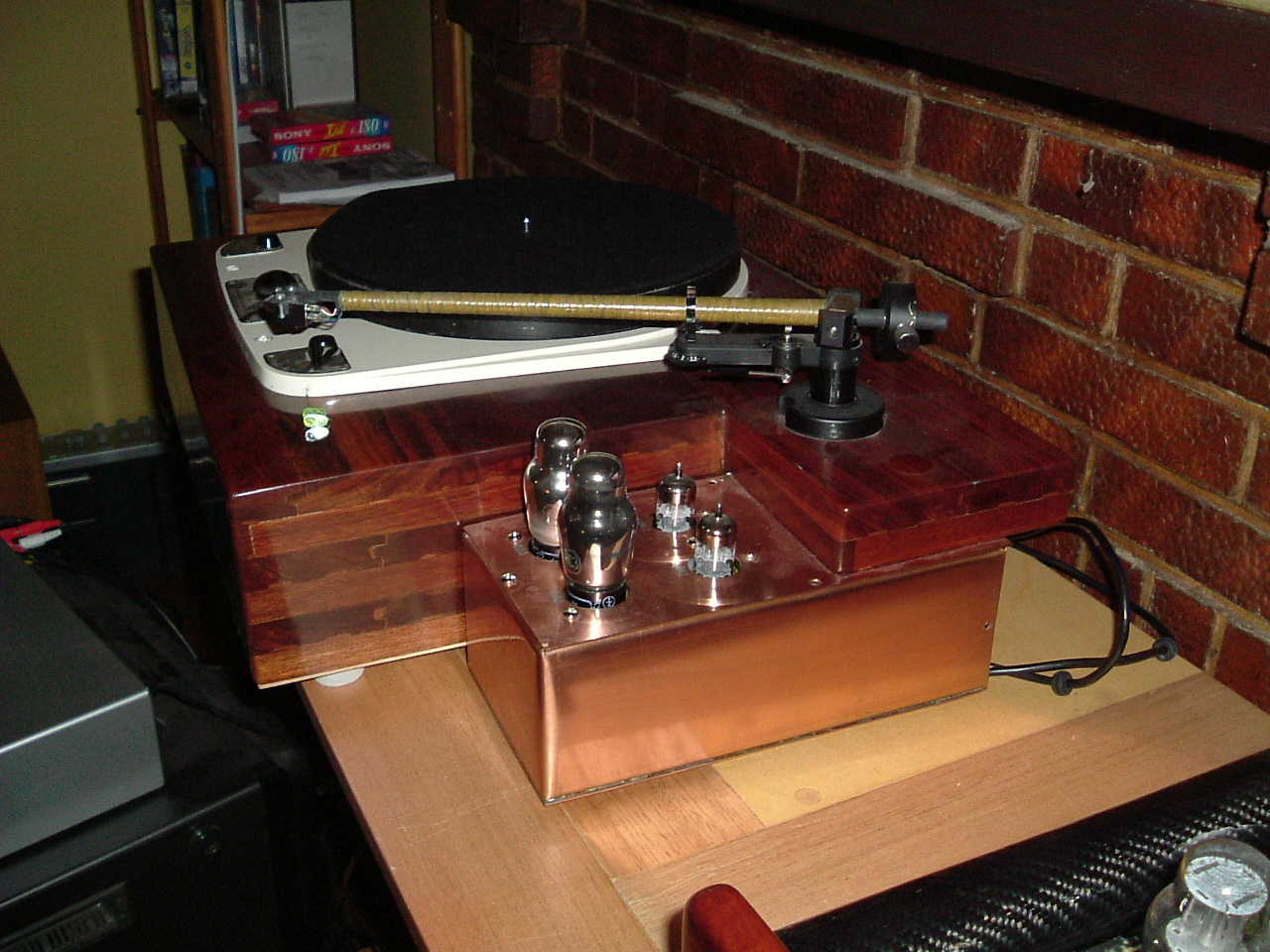
Click for full-size photo
I built this thing into a copper box measuring 260 x 130 x 90mm which attaches under the tonearm mount on my turntable. The box is a half-clamshell construction - the top and back of the box are one piece and are mounted directly to the turntable plinth. The front and sides are another piece and the bottom a third. The bottom sheet is soldered to the sides and front and then this assembly is attached to the top with 4mm machine screws which anchor into small aluminium blocks.
The FET stage, including CCS load, is built onto two small circuit boards which are attached to the back wall of the copper box with the tonearm wires soldered directly to these circuit boards. The power supply and the signal output for these boards are taken to a D-9 computer plug which mates with a D-9 socket on the main V/T chassis. You may scoff at the use of cheap computer hardware but these things are made to a quite high specification and work extremely well. They're cheap because they're made in the millions and there are no audio trade markups along the way.
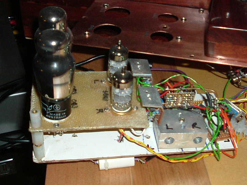
The main part of the amp is mounted on a fibreglass board with the vacuum tubes on a Kevlar/glass sub-board with appropriate sockets so that the tubes come up through the top of the chassis - except for the 6021s. These are buried inside the amp to shield them from noise. These things are designed to be wired directly into the circuit so at first I did just that. The first time I had to make a change I rethought this and soldered the 6021s into a couple of 8 pin IC sockets which plug into another pair of IC sockets which are soldered onto the board.
As noted before, heat dissipation is quite important for these very small tubes so I mounted them in an aluminium holder which I made from two 40mm x 50mm x 12mm aluminum blocks. I clamped these together and then drilled two 10mm holes along the seam to form two semicircular furrows in each. I used silicone heatsink pads in TO264 size to line the furrows and then clamped the 6021s in the assembly. The aluminium block gets to about 70C in use but that is well below the rated bulb temperature of 220C. The block is mounted onto the fibreglass main board with a couple of shock mounts to reduce microphonic influence. It's also grounded to act as a shield.
The fibreglass board and Kevlar sub board mount to the copper chassis with M4 standoffs. The active CCS loads are mounted on small veroboard type circuit boards and soldered to the appropriate socket pins. The small ones for the 6021s can sit next to the V/Ts but the CCSs on the cathode followers dissipate quite a lot of power so I mounted the pass transistors on a couple of 20 x 30 x 3mm aluminium blocks which intern are mounted to the copper chassis.
There are six vacuum tubes, six CCS boards, the two FET boards and the two RIAA boards all in one small box. If I did it again I'd make the box larger because working in this confined space is a pain.
All the signal wiring is Kimber TCS copper with Teflon insulation, partially because it takes soldering iron abuse with equanimity. The resistors are mix and match - the cartridge load resistors are Vishay VSH types, the FET drain resistors are Caddock MK132s, the 6021 plate resistors are Meggitt MCP 5 watt and the RIAA resistors are Meggitt RC55 0.1%. The 1 meg resistors on the FET gates are Holcos, all the CCS resistors are ordinary metal films. Yes, it's a bit of a dogs breakfast, but the input stage resistors were chosen for their low noise, the RIAA resistors for tolerance and everything else was what I had on hand. The MCP 5 watts are a bit of a find; they are dirt cheap, sound great and are easily available from a couple of major suppliers here in Oz.
So how does this thing sound? Well it's now so long since I heard the previous incarnation (Thorens TD160 with the Grace cartridge and the Linn arm which gave its all in the cause of audio experimentation) that I'm probably not qualified to give much of an opinion. It's very quiet - no audible rumble and no audible "rush" or hum at normal volume levels. Good records sound very good indeed. Bad records sound pretty bad. One favoured recording of which I have both a very good LP pressing and the CD transfer - The Dupre/Barbirolli recording of Elgar's Cello Concert sounds much richer, fuller and truer to life on LP than on CD.
© Mark Kelley 2004. All Rights Reserved.