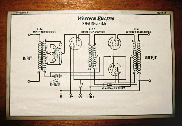
Factory schematic on the wood enclosure of a Western Electric 7A
Long-Distance Repeater Amplifier (photo by Kevin Carter).
Western Electric - Rosetta Stone for Triodes
A few years ago I bought a small book, "Audel's Radioman's Guide," by Edwin P. Anderson, copyright 1939. In addition to the antique technology ... like an aircraft control tower that features the all-new "Aircraft Radio" technology, but no radar or air-conditioning ... there are interesting circuits for electronics. The most intriguing circuit in the book is the Western Electric 92A amplifier on pages 426 and 427. The book is compact, no more than 4 3/4" inches by 6 1/2", so a magnifying glass is needed to examine the schematic in detail. A close look is rewarded by a very interesting circuit for the driver and the output section.
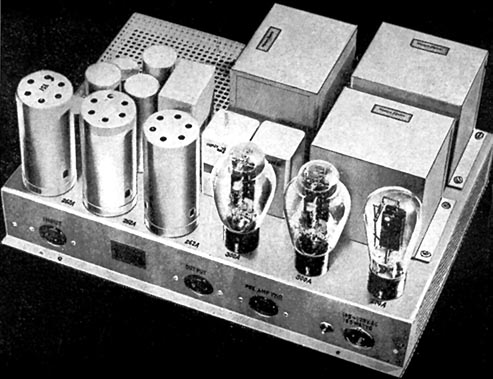
This photograph dates the WE 92A to 1935, with clearly visible 300A and 274A tube markings on the chassis. The 300A was only in production two years, and was replaced by the electrically identical 300B in 1936.
Western Electric 92A Public Address AmplifierThe single-ended 262A driver of the WE 92A uses parallel-feed transformer coupling to the push-pull 300A output stage. The DC supply to the 262A plate comes from R10, a 100K plate-load resistor, which is connected to a 10K/8uF RC filter and a 355V secondary B+ supply.
The AC signal path goes through the primary of the 285B interstage transformer and C1-C, a 0.5uF cap, and returns not to ground, as might be expected, but the cathode of the 262A driver tube. The cathode is biased by 2750 ohm resistor and bypassed by C2, an 8uF oil cap. The WE 92A driver uses both parallel-feed and a return cap that goes to the cathode of the tube. Note also that the cathode has additional bypassing, with the ratio between C1-C and C2 selected to minimize power-supply noise.
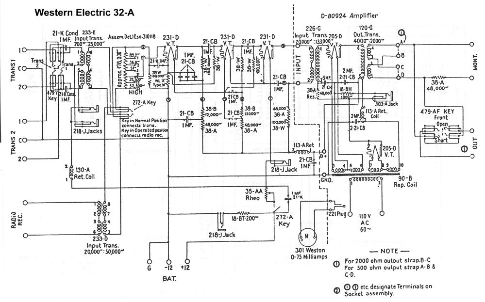
Western Electric 92A Parallel-Feed DriverA similar parallel-feed circuit is found in the Western Electric 32A, which appears to predate the WE 92A by at least a decade. The 205D, a direct-heated triode introduced in the early Twenties, is plate-loaded by the 113-A Retard Coil, otherwise known as a plate choke. The primary of the output transformer is returned through a 2uF capacitor to the virtual cathode of the 205D (the center tap of the filament supply). Although not immediately obvious, the 205D is biased through a 1K ohm resistor that returns to ground through the 303-A current-metering test jack (normally closed).
There is no cathode-bypass capacitor; instead, the grid is bypassed to ground through a 0.5uF capacitor. This is only possible with an input transformer, since the entire secondary "floats" and doesn't need to referenced to ground. The floating secondary provides a differential drive to the grid/virtual-cathode input pair of the 205D. The usual RC-coupling practice of AC-grounding the cathode masks the fact that tubes respond to a differential drive between the cathode and grid. This circuit takes advantage of the higher impedance grid circuit to reduce the size of the typical cathode-bypass capacitor. (Bypass caps are sized to match the impedances of the circuit they are bypassing. Cathode impedances are the lowest-impedance node of a vacuum tube, so the cathode-bypass cap must be the largest.)
Western Electric 32A Parallel-Feed Output SectionThe input circuit mirrors the output circuit, with the return side of the transformer connected not to ground, but the cathode. Since all 4 pins of the 205D are transformer-coupled, the nodes don't have to meet at ground, as they do in an RC-coupled circuit. In the WE 32A, they all meet at the virtual cathode of the 205D output tube.
Although this level of complexity might seem a little mind-boggling, keep in mind the WE 32A predates the invention of rectifier tubes ... the single 205D acting as rectifier for the complete WE 32A amplifier is evidence of that. The use of a single 205D as a half-wave rectifier, instead of using a pair for a much quieter full-wave rectifier, is an indirect comment on the lack of bass in the monitor speaker and the cost of each 205D. Click here for the complete Western Electric 32A schematic, which appears to be a monitor amplifier for a radio station.
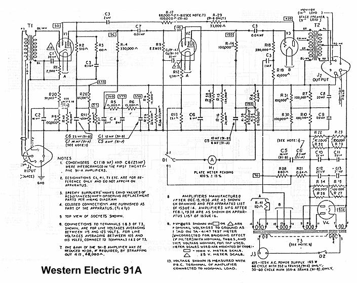
Western Electric 92A Output SectionMoving forward to the mid-Thirties, there are some interesting things going on in the Western Electric 92A push-pull output section. First off, the 300A power triodes are cross-coupled by a pair of 15pF (uuF in the old days) RF caps. In principle, these caps cancel out (neutralize) the Miller capacitance of the 300A's, increasing the bandwidth and slew rate of the PP triode pair.
Since the 92A output section was the inspiration for the Amity project, I tried many different values of neutralizing caps. Unfortunately, the square-wave response for every cap, no matter what value, had more overshoot and ringing, not less. Neutralization does not appear to be a "one-size-fits-all" approach. It's also possible that the modern wideband transformers used in the Amity don't benefit from neutralizing.
The most interesting feature of the WE 92A output section is the re-appearance of a coupling cap (C5+C6, R17 voltage divider) between the center-tap of the output transformer and the virtual cathode of the 300A's, and even more intriguing, a cap-coupled (C1-D) voltage divider (R13, R14) between the center-tap of the interstage transformer and the virtual cathodes.
This circuit might be the long-sought "Harmonic Balancer" invented by Western Electric. Although it looks at first blush like feedback, it operates quite differently than the usual overall loop feedback. For one thing, it doesn't do anything at all if the circuit is perfectly balanced ... the AC currents flowing between the center-taps of the two transformers will be zero. It only acts on unbalance currents that flow across the PP stage. In other words, the feedback is fully effective if one tube is pulled out of the circuit, and in practice helps to balance the PP pair of tubes under dynamic conditions. As with the neutralization technique described above, you need to make careful measurements under different drive levels, including deep clipping, to determine the right ratios of capacitors and the voltage divider.
Click here if you want the complete Western Electric 92A schematic. Fair warning: it's a large GIF, 3325 by 1750 pixels, so make sure your browser (and printer) can handle big images. (Computer memory is cheap now; buy a Gigabyte for less than $200!)
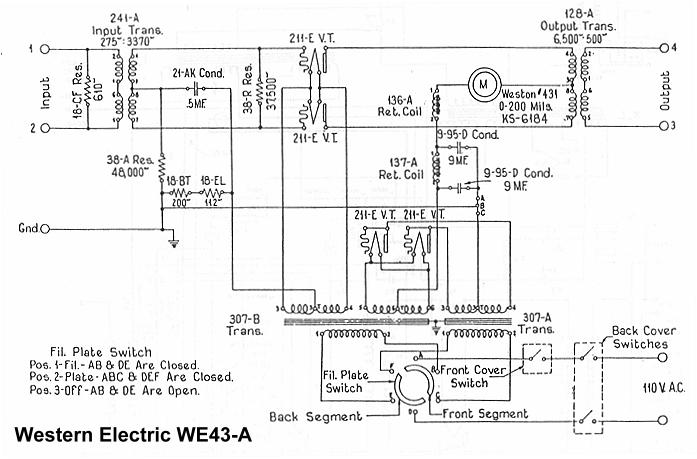
Western Electric 43A Movie-Sound AmplifierThe direct predecessor of the 92A was the 43A, the theatre amplifier used for the first sound movies. The first "talkies" employed a mechanically synchronized sound-on-disc system instead of the later sound-on-film system. The results of the projectionist playing the wrong 78 rpm record with the wrong reel of film can only be imagined. Mixups of this kind, along with the inevitable dropped records, must have put tremendous pressure on RCA and Western Electric to perfect the sound-on-film system of the early Thirties.
The reasons for the creation of the 300A/B power triode, 274A/B rectifier, WE 86B, and WE 92A amplifiers are clear when you look at the WE 43A. There were no special-purpose rectifier tubes, so a second pair of 211E's were pressed into service as full-wave rectifiers. The 211E's required a much higher B+ voltage than the 300A/B's that replaced them, as well as a separate medium-power amplifier as a dedicated driver stage. The three-position OFF/Fil/Fil+Plate power switch gives the projectionist the option of gently pre-heating the 211E filaments before applying full B+ power to the plates (similar to radio transmitter practice).
The 136-A retard coil on the center-tap of the output transformer is interesting. This acts as a constant-current source in the audio band, forcing the 211E pair into balance and preventing Class AB or Class B operation. The 43A also uses the same grid-bypass capacitor seen in the other Western Electric amplifiers.
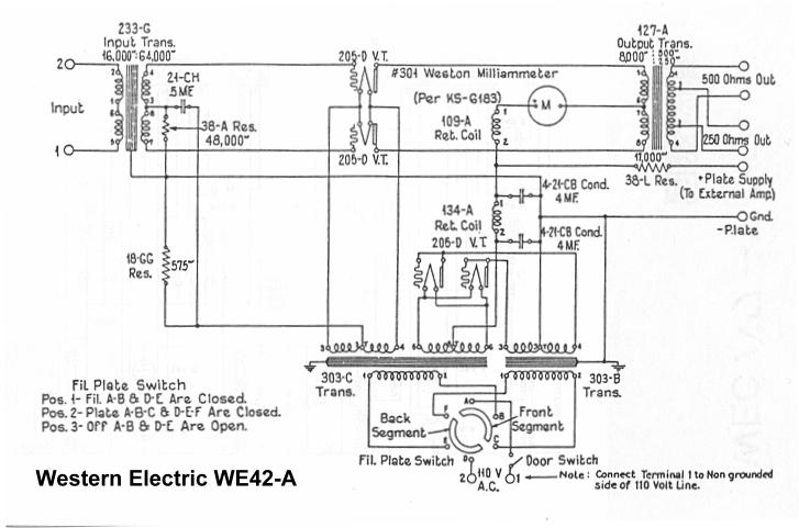
Although the WE 42A schematic appears remarkably similar, the 42A is a Beauty (modest B+ voltages and sweet-sounding "tennis-ball" 205D's), while the 43A is a Beast (more than 1KV B+, big iron all around, and four big transmitter tubes).
Those of you with low-efficiency speakers (88dB or less) should resist the siren song of the 211. Combining good sound, high inductance output transformers, and RF-transmitter high-voltage parts and construction technique is not a simple weekend project, even for the experienced engineers of Western Electric. The bright-emitter tubes look sexy, lighting up the room the way they do, but getting them to work in a good, reliable, and useful circuit is not easy.
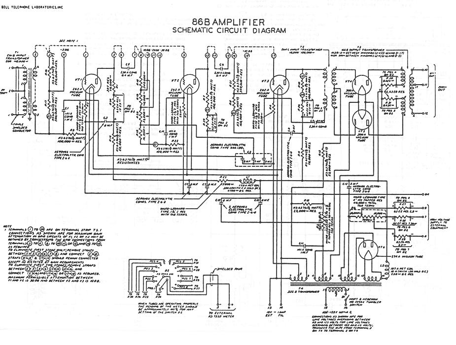
The 300A/B medium-power triode, 274A rectifier, and the 86A/92A amplifier family were specifically designed to replace the huge 42A/43A equipment rack you see on the right side of the page. That's right, a single Western Electric amplifier replaced this entire rack (which represents no more than one channel of 20-watt amplification). In practice, the rack stayed behind, and was filled with a pair of 86B, 91A, or 92A amplifiers. Not for stereo, of course, but for immediate changeover if one amplifier failed in service. By the mid-Thirties movie-sound was no longer a novelty, and reliability and good fidelity were expected.
Before we go off the deep end on Western Electric, keep in mind the original WE amplifiers were designed in an era when all musical sources (movies, records, and AM radio) were restricted to 40 Hz to 12 kHz bandwidth at most, with 100 Hz to 5 kHz being much more common. So don't expect an original Western Electric transformer set ... or modern reproductions ... to have bandwidths of 20 Hz to 20 kHz. It's not going to happen. Nor should you expect original WE amplifiers to meet modern expectations for hum and noise ... the speakers of the day almost never went down to 60 Hz, and the word "High Fidelity" was still a novel concept. It's not so much WE collectibles that are fascinating, but the superbly engineered circuits. Some impressive thinking went in to what appear to be minor aspects of the Western Electrics, things that have been forgotten by modern high-end designers.
Seventy years later, the technical reasons for parallel feed are as compelling as ever. Parallel feed allows a substantial reduction in core size in a SE transformer, and this in turn reduces stray capacitance, improving HF response as much as one or two octaves. Distortion goes down as well, since the core no longer has to accept a heavy DC current, which uses up most of the "permeability allowance" of the core. With no DC flowing through a primary, the transformer designer can take advantage of low-distortion cores that would be unusable for conventional SE or even PP applications, such as high-nickel, mu-metal, amorphous, or even more exotic materials.
Connecting the return of the primary to the driver-tube cathode gives a further improvement by shortening the AC loop around the audio circuit; in addition, careful ratioing of the cathode-bypass and transformer-return capacitor can essentially cancel most power-supply noise. (A vacuum tube amplifies the difference between the cathode and the grid; if noise that appears at the plate can be reduced in the right ratio at the cathode, it will cancel PS noise appearing the plate.)
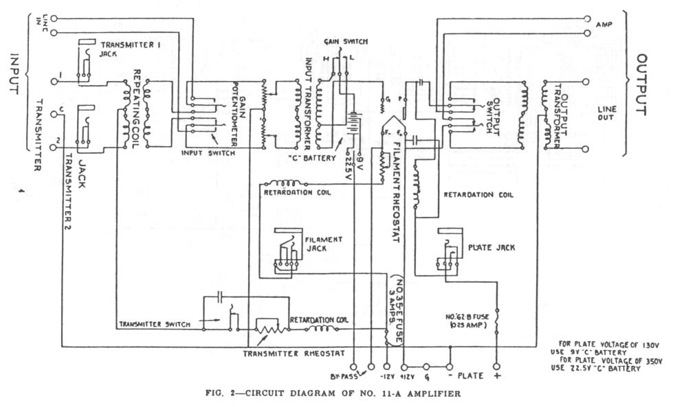
The Western Electric cathode-coupled parallel-feed circuit has been around for a long time; it predates the invention of indirect-heated triodes, power rectifiers, pentodes, and negative feedback. It's right there in the WE 11A, an amplifier from the dawn of radio in the early Twenties. Instead of coming up with clever "audiophile" names, I'd like to nominate Western Electric coupling as the title for this circuit. They did it first, they might as well get the credit.
For more Western Electric circuits, visit the Loop Distortion presentation that I gave to the Bay Area Tube Enthusiasts on June 1st, 2003. In addition to a variety of unusual topologies not seen in commercial audio since the 1930's, there is an analysis of the paths audio currents take in working circuits - there's more going on than the usual "signal path" that audiophiles think of. Not surprisingly, the telephone company, with their long experience with audio, transformer coupling, and long-distance signal transmission, got there first.
The picture at the top of the page shows a WE 7A dating from 1922, at the dawn of electronic amplification. When you picked up a phone and asked for "Long Distance", that's the circuit that amplified your voice and sent it to the next city, over many miles of twisted-pair wire. Wonder where the phrase "line stage" comes from? You're looking at one of the first ones ever made - the "line" refers to a telephone line, not a component sitting two feet away. Telephone practice migrated to studios and radio stations, which used the services of AT&T Long Lines to build the first radio networks.
Direct-heated triodes, transformers, and non-feedback circuits were forgotten when the Williamson wiped out all other amplifier topologies in the years from 1948 to 1956. True, you see the occasional Quad II or McIntosh, but almost all other amplifiers, both commercial and hobbyist, stayed very close to the Williamson. The sum total of innovation was substituting cheaper parts - 12AU7's for 6SN7's, any transformer other than Partridge, and any pentode other than the original, triode-connected GEC KT66's.
In the years following 1955-58, innovation slowly started up again - the Dynaco simplification (deleting the driver stage and substituting EL34's), the all-differential Acrosound (borrowing from oscilloscope technology), and a broader variety of circuits in the early Sixties. Then came transistors, and a few years later, the destruction of the American consumer electronics industry. Many years later, after the ups and downs of high-end audio, the boutique years of the Eighties, and the vacuum-tube renaissance of the Nineties, we can look back on the span of audio engineering with a longer perspective.
The long-lost ideas and concepts from Western Electric are finally being brought to light by members of the K&K Audio Forum and the Bay Area enthusiasts. Does they sound different? Try it for yourself! I'd also like to give a big Thank You to YS Audio of Hong Kong for the on-line library of Western Electric and other classic circuits (with Java active, click on World Circuits to see the library).
Return to the Library
Text © Lynn Olson 2001. All Rights Reserved.